


 152 / 237

X2. INSTRUCTIONS FOR USE OF DESIGNS IN TABLE X1.1
X2.1 Each section can be designed individually but in an
effort to save time select the section that carries the heaviest
loads and use it for the whole box.
X2.1.1 Assume the height of each section based upon the
size and location of pipes entering or leaving the box. The
designs in the tables assume continuity of steel around the box.
If a hole is made in a section, there should be concrete above
and below and sufficient additional reinforcing to transfer
forces across the opening.
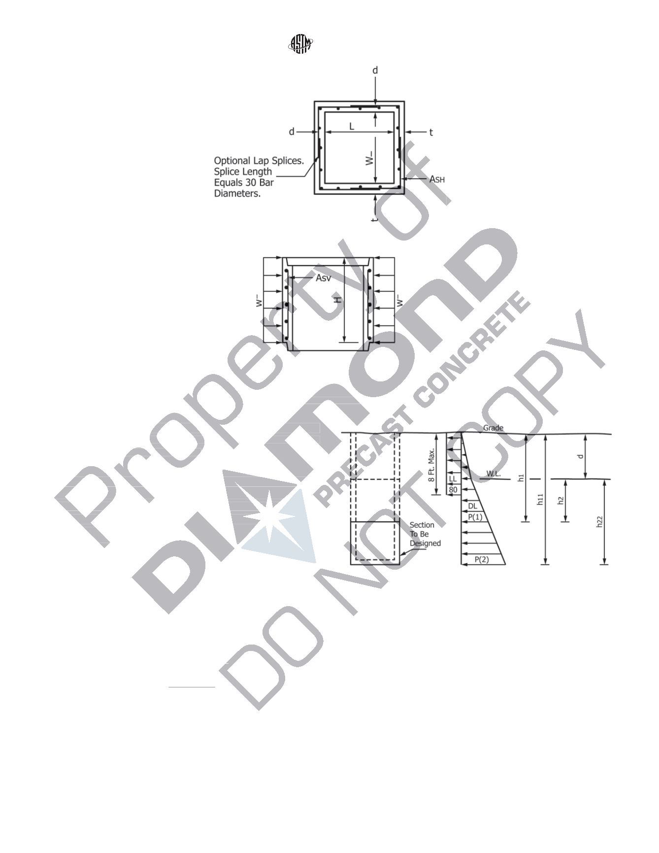
X2.1.2 Determine depth of section to be designed (
h
1
and
h
11
in
Fig. X2.1
).
X2.1.3 Determine depth of water table (
d
in
Fig. X2.1
).
X2.1.4 Assume a lateral soil pressure of 40 psf/ft of height
and water weighing 62.4 lb/ft
3
.
X2.1.5 From
Fig. X2.1
:
P
~
1
!
5
40
h
1
1
62.4
h
2
(X2.1)
P
~
2
!
5
40
h
11
1
62.4
h
22
P
5
P
~
1
!
1
P
~
2
!
2
X2.1.6 Choose a Class (300, 500, 700) with capacity greater
than
P
. Enter the table with desired size to obtain wall
thickness, amount of reinforcing steel, and location of steel in
the wall.
FIG. X1.2 Section AA
FIG. X1.3 Section BB
FIG. X2.1 Depth of Section
C913 − 08
5
Copyright by ASTM Int'l (all rights reserved); Mon Jun 29 17:07:04 EDT 2015
Downloaded/printed by
Jed Friesen (Predl Systems) pursuant to License Agreement. No further reproductions authorized.