


 151 / 237

APPENDIXES
(Nonmandatory Information)
X1. DESIGNS FOR RECTANGULAR BOXES
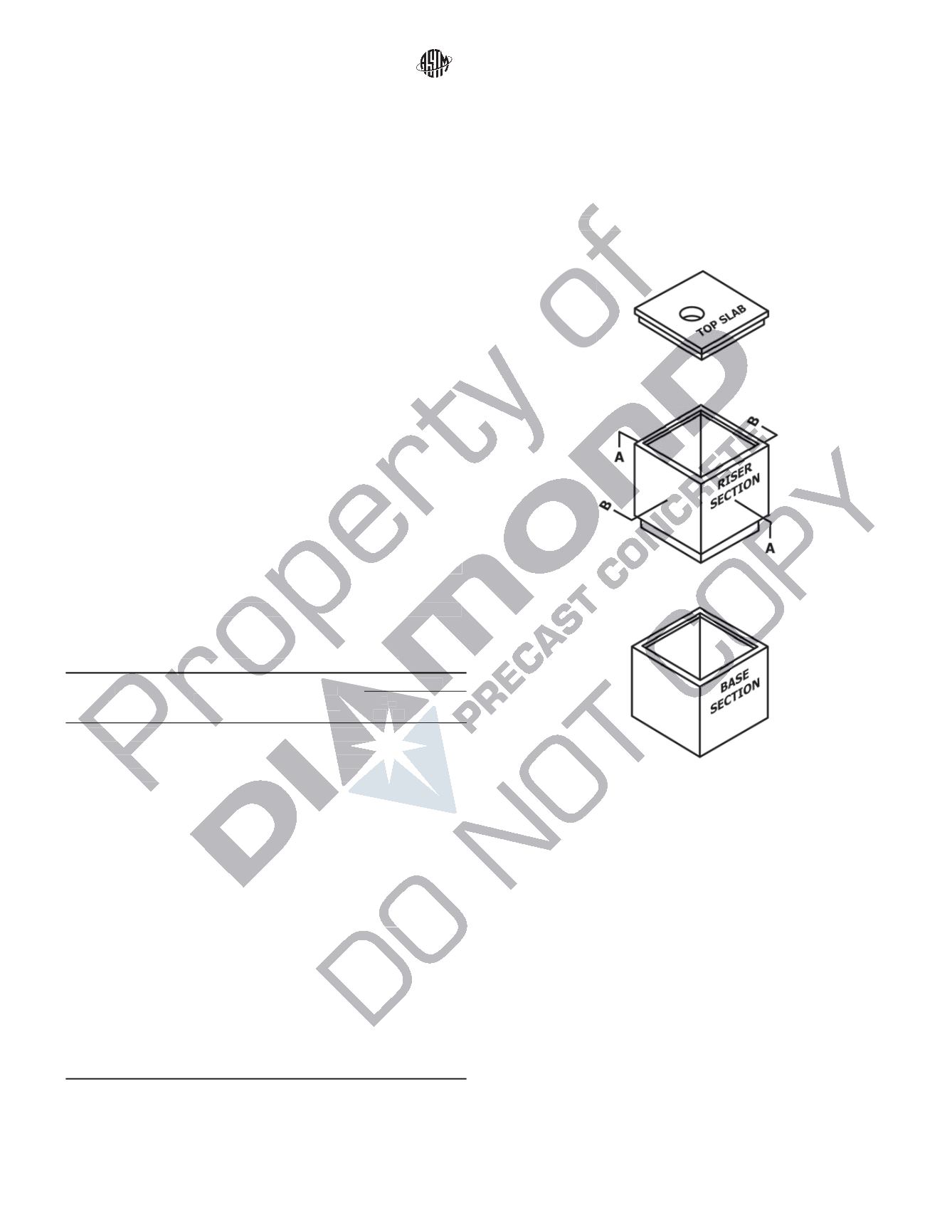
X1.1 Description of Designs
X1.1.1 The designs in
Table X1.1
are provided as a conve-
nience for specifying, purchasing, and manufacturing. Riser
and base sections are shown in
Fig. X1.1
.
X1.1.2 The successful performance of the product depends
upon the proper selection (based on field conditions), good
manufacturing practices, and proper installation.
X1.1.3 Refer to
Appendix X2
for instructions on the use of
the designs.
X1.2 Structural Analysis
X1.2.1 The analysis is based on the slope-deflection solu-
tion of a frame with nonprismatic members.
X1.2.2 Loads are based on Practice
C890
.
X1.3 Design Calculations
X1.3.1 The concrete shall be designed to be proportioned
for
f
c
' = 4000 psi (28 MPa).
X1.3.2 Reinforcing steel shall be Grade 60 (minimum yield
strength of 60 000 psi) (3.84 MPa).
X1.3.3 The strength design method described in ACI-318 is
used with U.L.F. = 1.7.
X1.3.4 Minimum reinforcement is 0.002 times the gross
concrete area of the cross section.
X1.3.5 Calculations for units with integral slab (top or
bottom) do not take into consideration rigidity or support from
slab.
X1.4 Definitions
X1.4.1
t—
Total thickness of wall (
Fig. X1.2
).
X1.4.2
d—
Distance from centerline of horizontal steel to
inside face of wall (
Fig. X1.2
).
X1.4.3 A
sh
—
Area of horizontal steel per vertical foot (
Fig.
X1.2
).
X1.4.4 A
sv
—
Area of vertical steel per horizontal foot (
Fig.
X1.3
).
X1.4.5
Class—
a term that can be used to describe the
product, for example, 300, 500, 700. The number also refers to
the capacity of the unit in terms of lb/ft
2
(Pa).
TABLE X1.1 Designs for Rectangular Boxes
A
Size
L by W
t (in)
d (in)
Class
w (psf)
Reinforcing
A
sh
(in.
2
/ft)
A
sv
(in.
2
/ft)
2 ft by 2 ft
6
3 300 500 700 0.14 0.14
2 ft 6 in. by 2 ft
6
3 300 500 700 0.14 0.14
2 ft 6 in. by 2 ft 6 in.
6
3 300 500 700 0.14 0.14
3 ft by 2 ft
6
3 300 500 700 0.14 0.14
3 ft by 2 ft 6 in.
6
3 300 500 700 0.14 0.14
3 ft by 3 ft
6
3 300 500 700 0.14 0.14
3 ft 6 in. by 2 ft
6
3 300 500 700 0.14 0.14
3 ft 6 in. by 2 ft 6 in.
6
3 300 500 700 0.14 0.14
3 ft 6 in. by 3 ft
6
3 300 500 700 0.14 0.14
3 ft 6 in. by 3 ft 6 in.
6
3 300 500 700 0.14 0.14
4 ft by 2 ft
6
3 300 500 700 0.14 0.14
4 ft by 2 ft 6 in.
6
3 300 500 700 0.14 0.14
4 ft by 3 ft
6
3 300 500 700 0.14 0.14
4 ft by 3 ft 6 in.
6
3 300 500 700 0.14 0.14
4 ft by 4 ft
6
3 300 500 700 0.14 0.14
4 ft 6 in. by 2 ft 6 in.
6
3 300 500 700 0.14 0.14
4 ft 6 in. by 3 ft
6
3 300 500 700 0.14 0.14
4 ft 6 in. by 3 ft 6 in.
6
3 300 500 700 0.14 0.14
4 ft 6 in. by 4 ft
6
3 300 500 700 0.14 0.14
4 ft 6 in. by 4 ft 6 in.
6
3 300 500 700 0.14 0.14
6 ft by 5 ft 6 in.
6
3 300
0.14 0.14
6 ft by 5 ft 6 in.
6
3
500
0.17 0.14
6 ft by 5 ft 6 in.
6
3
700 0.24 0.14
6 ft by 6 ft
6
3 300
0.14 0.14
6 ft by 6 ft
6
3
500
0.18 0.14
6 ft by 6 ft
6
3
700 0.27 0.14
A
One in. = 25.0 mm.
FIG. X1.1 Typical Assembly
C913 − 08
4
Copyright by ASTM Int'l (all rights reserved); Mon Jun 29 17:07:04 EDT 2015
Downloaded/printed by
Jed Friesen (Predl Systems) pursuant to License Agreement. No further reproductions authorized.